The PMIC Load and Line Transient Response Plugin
The PMIC Load and Line Transient Response SIVA plugin allows companies making Power Management ICs (PMICs) to use their existing test equipment to evaluate and characterize the PMIC’s transient response to sudden changes in Load current or Line Voltage.
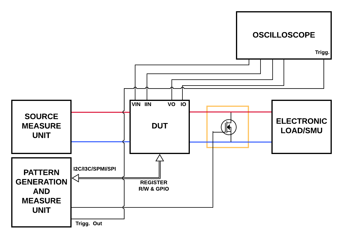
Figure 1. Test setup for the Load and Line Transients Measurements
The plugin requires the following four instrument types. For each type the PMIC specifications will dictate the model that works best. However, provided it has remote programming capability, the instrument can be ‘mapped’ to be used by the plugin. The four instruments are:
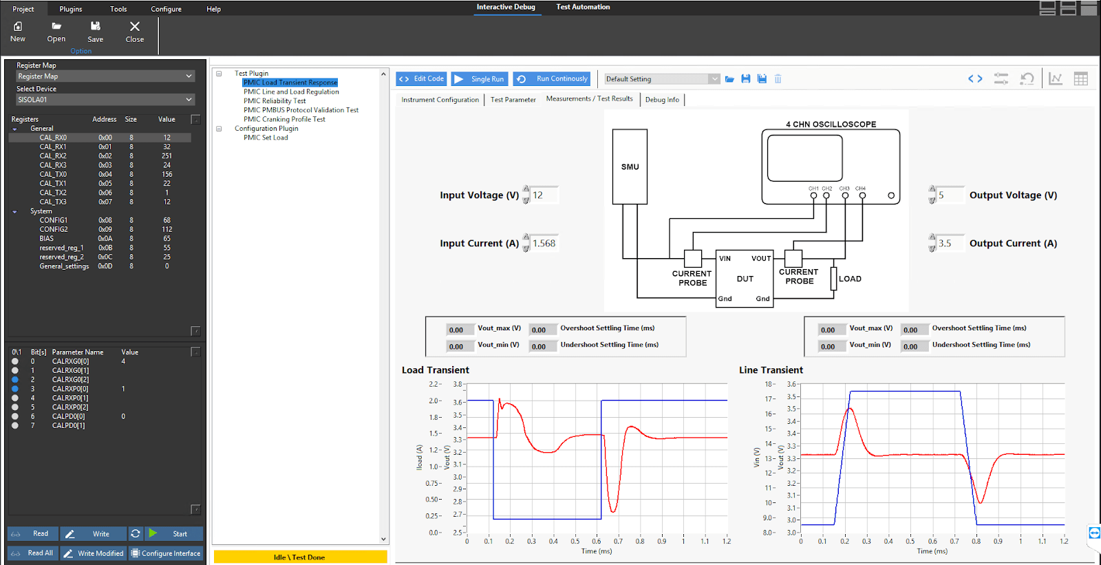
Figure 2. Front Panel of the Load Transient plugin
The PMIC Load Transient Response plugin takes advantage of the Hardware Abstraction Layer functionality built in to SIVA framework which makes it easy for a test engineer to use measuring instruments from any vendor. The HAL concept is illustrated in Figure 3.
Figure 3. The Hardware Abstraction Layer (HAL) built into SIVA makes it possible for the PMIC Load Transient Response plugin to work with instruments of the same type from any manufacturer.
The Hardware Abstraction Layer encapsulates the instrument driver/API and presents the measuring instrument from any manufacturer appear as a generic device. The front panel controls provided by the HAL allows the test engineer to set up measurement limits and ranges easily and with minimal time.
Figure 4. Test Settings for the Load Transient plugin
The Test Parameters tab contains input fields for setting the range over which the different load and line current/voltage parameters are to be varied and the number of steps.
What advantages does using the PMIC Load Line Transient Response SIVA Plugin afford the user over building his or her own test code for Load and Line Transients?
Also available as a separately sold add-on to the PMIC Line and Load Transients Plugin is DIVE, a waveform tagging, learning and analysis tool that uses Machine Learning Models to simplify the waveform analysis for typical PMICs. One can train DIVE to classify the waveform scope-shots from the PMIC output terminals as NORMAL/ANOMALOUS/DEFECT1 etc.Some thematic diagrams and screenshots are shown below.
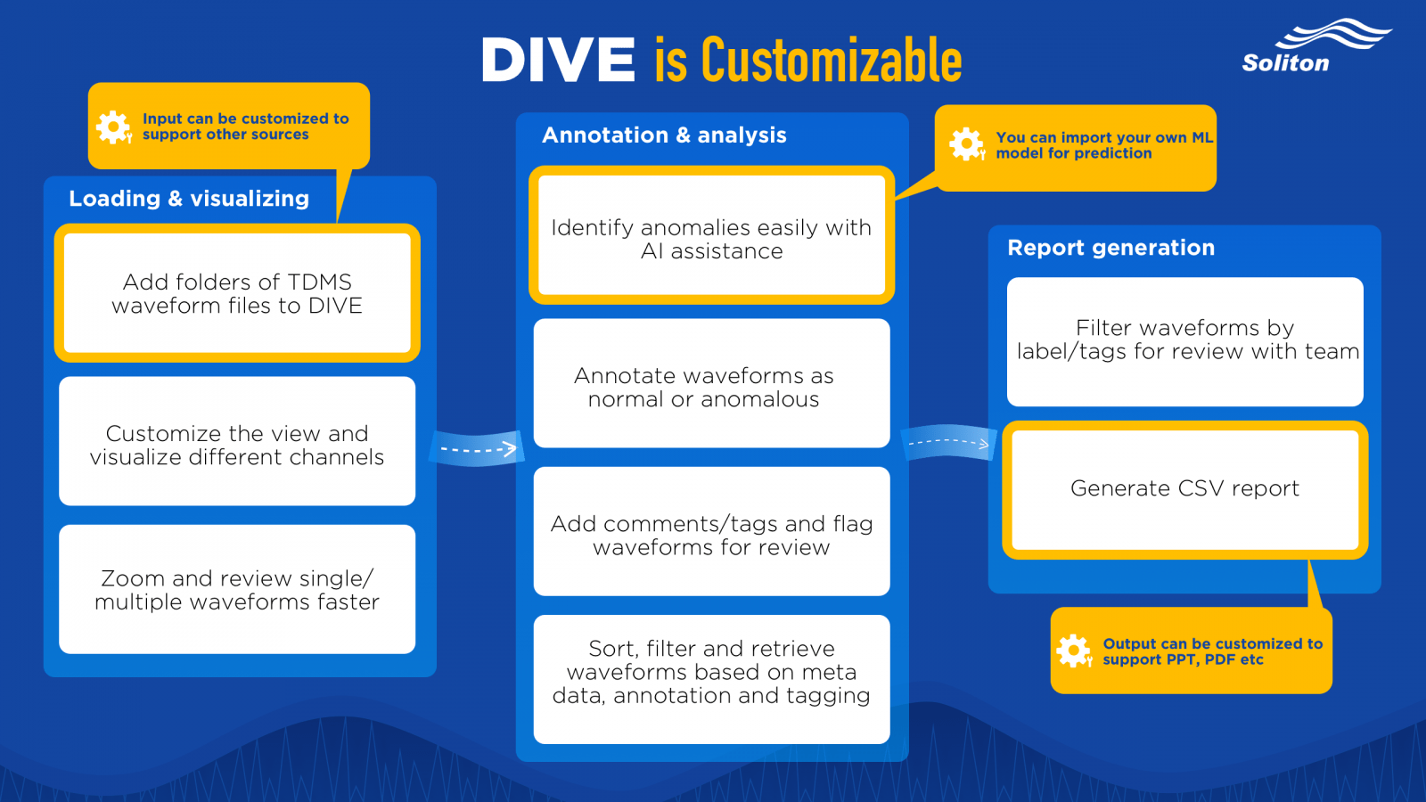
Figure 5. Workflow and Capabilities of DIVE.
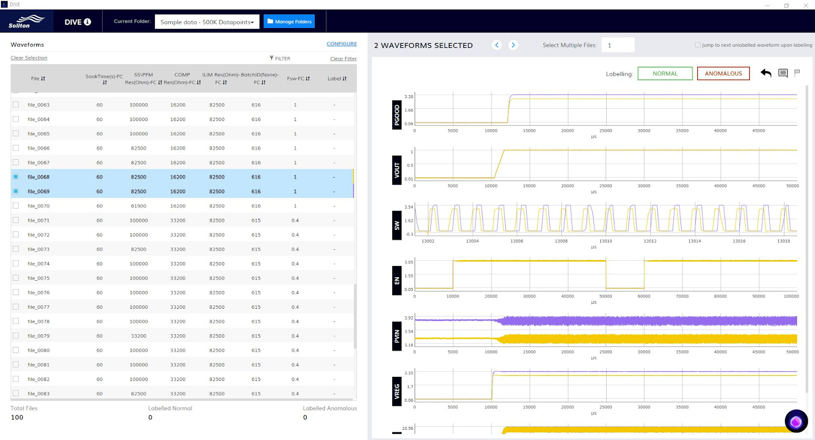
Figure 6. PMIC Switching regulator waveform analysis in progress using DIVE.
*Click below button to Download SIVA Framework Introduction
Please fill in the following form and get access to download SIVA Framework Introduction
Please fill in the following form and get access to I2C Parametric Validation Suite & Service quotes.
Error: Contact form not found.
Please fill in the following form and get access to I2C Validation Suite Demo.
Error: Contact form not found.
Please fill in the following form and get access to I2C Parametric Validation Suite Product Sheet.
Error: Contact form not found.
Please fill in the following form and get access to I2C Test List & Report Format.
Error: Contact form not found.
Please fill in the following form and we shall get in touch with you soon to set up a demo of the requested service/product. Thank you!
Error: Contact form not found.
Fill in this form and submit for your download to start automatically
Error: Contact form not found.
Submit this form and the PRIM Brochure document will be sent to your email.
Error: Contact form not found.