ICs that have multiple input power rails will only wake up successfully if certain constraints are satisfied in terms of the order, ramp rates and voltage levels of those input rails.
“The consequences of improper power-up are often very subtle, seemingly unrelated to power-up and result in very significant debugging and troubleshooting time.”
These situations have led IC companies to consider ways to systematically sweep variables such as the order, ramp rate and voltage levels of the different input rails and identify startup constraints so they can be documented and customers can be advised.
Today’s high-performance processing devices, such as FPGAs, DSPs, ADCs, and microcontrollers require multiple voltage rails just to power their own internal circuitry, such as the core, memory, I/O, etc. When the processor or the complex device is powered on, the on-chip power-on circuitry must be able to initialize and function while the rest of the chip is inactive. The circuits are within multiple power supply domains, and depending on the supply configuration, these power supplies may be activated at different times. This is why a systematic and modular approach to powerup validation is very useful. This could help identify all the conditions under which the chip would not power up correctly and either correct the issue or specify the constraints in the documentation provided to the customer.
Soliton has provided solutions for sweeping the power-up rail order, rail slew rate and power up delays for devices with multi-rail power supplies.
These solutions are based on a LabVIEW built scalable framework with NI PXI hardware modules. The PXI modules are scalable and future-proof. The modules can be added to the system based on the Analog and Digital stimulus specifications and the manner in which we will verify successful power up. Modules used were PXI SMU modules, Analog Input, Analog Output, Digital IOs, HSDIO, and the latest Digital pattern generator cards. The software can provide configurability for
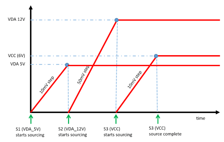
- Analog -> Setting the voltage transition to a specified voltage, at the specified time offset, ramp rate of the transition, brownout condition, etc.
- Digital -> Used both for simulating any input digital signals that play a part in the power-up sequence and also for emulating digital protocol based commands that can query the DUT to ascertain if it has woken up fine.
Starting with the normal startup order, delay and ramp rates as a baseline, the solution should be able to sweep these three configurable parameters across the specification range or beyond (based on the need) and have multiple ways to validate if the device is properly powered up and works as expected, like reading a digital ‘Power Good’ pin’s state or reading registers to check if the device has powered up as expected. The sweeping of the configurable parameters can be optimized using various techniques. The debugging of the failure conditions can also be optimized by algorithms that quickly identify regions of this parameter space (ramp up rate, order and delays) causing failures.