

Validating Multi-Interface PMICs Without Losing Test Coverage
In recent years, Power Management IC (PMIC) architectures have changed sharply. Validating a PMIC interface used to mean setting up an I2C or SPI controller block, running basic register read/write sweeps, and checking a few timing margins on an oscilloscope.
Today, a single PMIC block regularly houses several heterogeneous interfaces: MIPI SPMI™ for low-latency dynamic voltage scaling (DVS), MIPI I3C® for high-throughput telemetry, alongside legacy I2C and SPI domains for housekeeping and safety.
Testing each bus on its own still proves each protocol works. What it no longer covers are the failures that happen when the interfaces interact, and that is where the coverage gap now sits.
The Reality of Multi-Interface Failure Modes
When several independent communication domains share a single die and a high-density pin footprint, they interact in ways that isolated protocol tests cannot capture. When validating these chips, engineers must actively look for three critical multi-interface failure modes.
1. Cross-Interface Crosstalk and Signal Corruption
In a multi-interface PMIC, noise flows in two directions.
Digital to analog: Fast buses such as SPI at 25 MHz or MIPI I3C SDR at 12.5 MHz switch with sharp edges. Routed close to the regulators' sensitive feedback loops, they can couple noise in, both capacitively (dv/dt) and inductively (di/dt), and disturb the output voltage the PMIC is meant to hold steady.
Analog to digital: The PMIC's own switching regulators are among the fastest-switching nodes on the die. Their edges can couple into slower open-drain I2C lines, which are easy to disturb because of their weak pull-ups and slow rising edges. Fast-mode and Fast-mode Plus devices filter spikes shorter than 50 ns, but longer glitches pass through.
In both cases, a burst of activity in one domain can show up in another as a false START/STOP condition, a corrupted bit, or an unexpected NACK.
PMIC designers mitigate this with isolation, layout and slew-rate control. But mitigation is design intent, not proof. The only way to confirm it holds on real silicon is to stress all interfaces together and watch the quiet ones.
2. Register Contention and Asynchronous Lockups
Each interface operates on its own asynchronous external clock domain. If the host processor issues a DVS voltage change over SPMI while a secondary microcontroller polls a temperature sensor over I2C, both transactions can reach the internal register arbitration logic within the same synchronization window. Poorly designed arbitration or synchronizer stages can result in:
- Stale or partial reads: a read returns old data, or a value that was only partly written.
- Register lockups: the digital core hangs and needs a hard power-on reset (POR) to recover.
3. Power State and I/O Leakage Permutations
Multi-interface PMICs frequently support split I/O voltage domains (for example, one bus at 1.8 V, another at 1.2 V). During low-power system sleep states, one domain may power down completely while another stays alive. If internal isolation cells are inadequate, current will leak from the active interface into the unpowered one, causing back-powering, latch-up or unexpected battery drain.
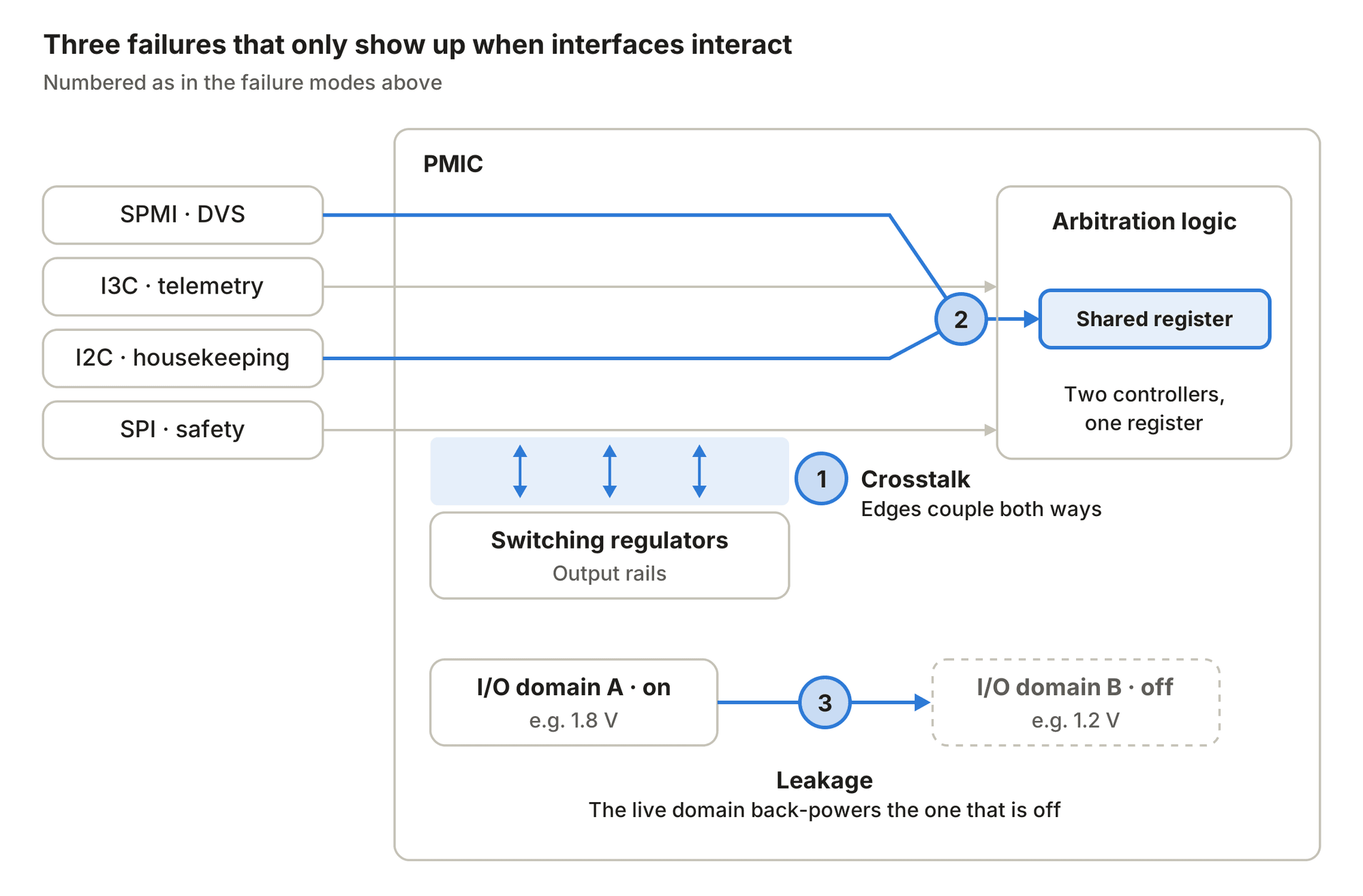
Each interface works on its own. Failures occur where they meet: in the shared register logic, between fast bus edges and the regulators, and across the split I/O voltage domains.
How to Build a Defensible Validation Strategy
To catch these asynchronous, multi-variable bugs before production release or system integration, validation teams need a test matrix that adds interaction tests on top of per-bus compliance testing.
Multi-interface test strategy | What it does |
Concurrent stress testing | Run maximum-throughput traffic on all buses simultaneously to force electrical crosstalk. |
Collision force matrices | Intentionally program masters to read/write to the same register addresses at overlapping intervals. |
Parametric boundary sweeps | Sweep interface I/O voltages, inject clock skews, and force bus timeouts across full PVT corners. |
1. Execute Concurrent Stress Tests
Don't stop at testing each bus in isolation. To validate electrical robustness, configure your test bench to drive maximum-throughput pseudo-random data across all interfaces simultaneously. Without concurrent traffic, the worst-case cross-interface crosstalk described earlier never occurs on the bench.
2. Force Collision Scenarios
Develop software test routines that intentionally force write/read collisions at the same memory locations across different physical ports. Vary the timing offset between the two bus masters in sub-nanosecond increments to sweep across the asynchronous clock domain boundaries.
3. Validate Low-Power Boundary Conditions
Systematically cycle through every permutation of interface power states (for example, Port A on, Port B off) while continuously monitoring the logic levels of the quiet bus and measuring leakage current down to the microamp level.
Accelerating Execution in the Lab
While designing this test plan is a logical engineering exercise, executing it manually is where teams run into a wall. Setting up multiple distinct protocol exercisers, linking them to a common trigger line, configuring oscilloscopes for parametric sweeps, and coding a custom automation framework in Python or LabVIEW can consume months of engineering effort.
This is where Soliton's Protocol Validation Suite (PVS) fits into a practical engineering workflow.
Instead of having your validation team spend half their development cycle writing, debugging and maintaining low-level driver code for multiple buses, PVS provides a configurable framework built specifically for post-silicon validation. Each test in the matrix above maps to a PVS capability: concurrent multi-bus traffic for crosstalk, adjustable bus timing for collisions, and adjustable I/O voltage thresholds for power-state boundaries.
- Native multi-bus coordination: PVS supports MIPI SPMI, MIPI I3C, I2C and SPI out of the box on a unified hardware platform. This makes setting up synchronised, concurrent stress tests a matter of configuration rather than custom code.
- Built for negative testing: PVS lets you inject faults, skew bus timing parameters and shift I/O voltage thresholds to sweep the parametric boundaries where clock domain crossing errors hide.
- Fits your existing automation: PVS plugs into your existing automation workflow through APIs for LabVIEW, Python and TestStand. Your scripts can coordinate PVS with environmental chambers and other bench equipment to run the multi-interface test matrix across full PVT corners. NI power supplies can be controlled directly from within PVS.
With the Soliton Protocol Validation Suite running the interaction tests, validation engineers get the coverage that per-bus testing misses, and spend their time on what those tests reveal rather than on building the bench that runs them.
Want to see how your PMIC's interfaces hold up when they run together? Talk to us.